
Plures Intelligens Modicum Machinatorem
808 Gilman Street Berkeley, CA 94710 | 510-549-3300 | admin@bearinc.com
Dr. Glen Stevick, P.E. ext. 101 | Dr. Dave Rondinone, P.E. ext. 102 | Derek King, P.E. ext. 103 | Mingxi Zheng, P.E. ext. 106 |
Metals.
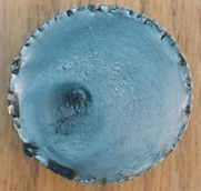
turbine blade failure
BEAR engineers determine the root cause of failure, not just the failure mode of metal structure. The turbine blade in the photograph to the left, for example, cracked due to creep. Creep is a common deformation of materials due to tensile stresses at high temperatures for long periods of time.

micrograph of turbine blade
BEAR engineers thoroughly analyze the surface of the products using a scanning microscope. A SEM micrograph (shown below) of the crack surface shows the intercrystalline fracture mode and voids, which are typical indications of creep failures. This turbine blade also had additional causes of failure after we examined the surface with optical microscopy. It showed that during service, the blade had been subjected to extreme temperatures, which were severe enough to cause melting.
optical micrograph of turbine blade
An optical micrograph of the blade (shown below) shows a void that resulted from melting of the metal underneath the protective coating. Centrifugal forces during service caused the melted metal to flow toward the edge of the blade, where it displaced the coating, at the yellow arrow. The coating then spalled off, leaving the blade unprotected and susceptible to creep damage.


sector shaft failure
Other recent investigations conducted at BEAR have focused on interpreting fractures and identifying the causes of failure. There were many possible factors of the failures, so we had to carefully eliminate certain suspected causes for failure. In this case, BEAR was asked to determine what was the cause of the accident of the shaft failure.
fracture surface of sector shaft
We found out that the fracture occurred from the steering mechanism on a truck, transporting a full load. The photograph shows the fracture surface of the sector shaft. The fracture surface had a circumferential smearing and a slightly off-centered final fracture zone.
side-view of sector shaft
The side view of the broken shaft shows a twisting deformation from torsional forces during fracture. The fracture showed no indications of fatigue cracking, which would possibly point to a defect in the shaft as the cause for failure in the beginning of investigation.
By interpreting the fracture features, we were able to determine that the failure was due to a single, torsional overload event. In other words, the shaft was subjected to a force during the accident that resulted in its failure.
